

Plan smart switch modules for new builds around the lighting load and wiring, not just the app or connection type. In Australia, fixed electrical installation must follow AS/NZS 3000, and a licensed electrician must install or replace smart light switches. Getting the choice right early helps make the controls part of the electrical plan from the start.
It’s easy to focus on whether a switch works with your preferred smart-home platform. The connected load matters just as much: a module designed for on/off lighting may not suit dimmable LEDs. The module, light fittings and wiring all need to be compatible.
This guide explains how smart switch modules work, how to match a module to common lighting loads and what to plan with your electrician before installation. It also compares module types and covers wiring considerations for a new build, helping you narrow down the right option for each lighting circuit.
Key Takeaways
- Plan switch locations and module wiring with your licensed electrician before construction is complete.
- Match each switch module to the lighting load and whether the circuit needs simple on/off control or dimming.
- Consider neutral-wire requirements early, as they can affect which module suits each circuit.
- Keep Australian electrical and wireless compliance in view when selecting smart switches for fixed installation.
- Compare Thread, Zigbee and Wi-Fi options against your home’s control preferences and lighting plan.
Electrical planning and licensed electrician installation
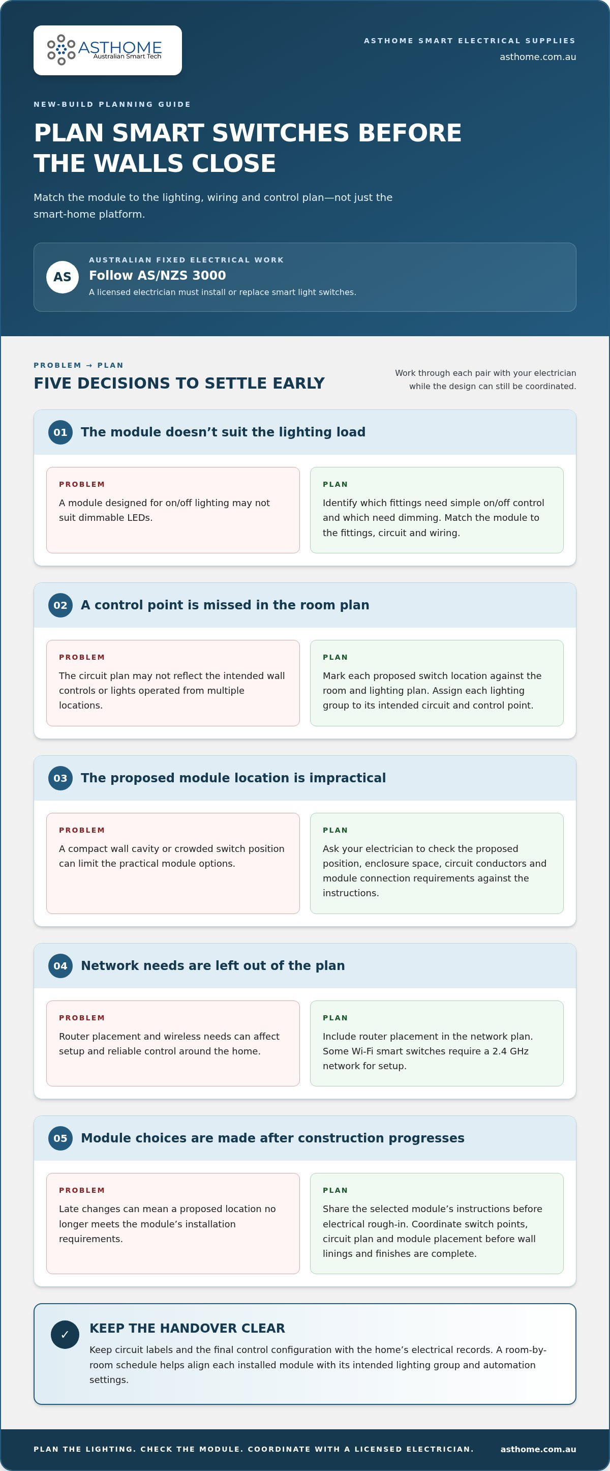
Plan smart switch modules alongside the lighting circuits, control locations and network setup. In Australia, fixed electrical work must follow AS/NZS 3000, and a licensed electrician must install or replace smart light switches.
Electrician checks and constraints
Before choosing a module, map each lighting circuit to its fittings and intended controls. Note whether each room needs simple on/off switching or dimming, and identify any lights controlled from multiple locations. Your electrician can compare the proposed setup with the circuit, module instructions and installation conditions. The module must suit its circuit and connected load, not just your chosen automation platform.
Include the router and wireless plan in the discussion. Some Wi-Fi smart switches require a 2.4 GHz network for setup, so note where the router will sit and which areas need reliable control. Treat the electrical installation as a safety matter. Don’t open or alter fixed wiring yourself; leave inspection, connection and testing to the licensed electrician.
Module fit and installation
A smart module needs a suitable location and enough space in its enclosure. Ask your electrician to assess the proposed switch positions against the module’s installation instructions. A compact wall cavity or crowded switch location can limit the practical options. The electrician also needs to account for the circuit conductors and the module’s connection requirements when finalising the layout.
Make this decision before wall linings and finishes are complete. Your electrician can then coordinate switch points, the lighting circuit plan and module placement during construction. For example, hallway and living-area lights might need separate automation groups, while retaining straightforward wall control in each space. The final configuration should reflect your lighting plan and the module’s documented requirements.
For a new build, work through these planning steps with your electrician:
- Mark every proposed switch location against the room and lighting plan.
- Identify which fittings need on/off control and which need dimming.
- Assign each lighting group to the intended circuit and control point.
- Share the selected module’s instructions before electrical rough-in.
- Include router placement and any 2.4 GHz setup needs in the network plan.
Keep the module specifications available during installation. Your electrician can compare the documented load requirements with the fittings on each circuit, then complete and test the fixed wiring. If the planned location doesn’t meet the module’s installation requirements, revise the design before closing the wall rather than improvising around a finished space.
Plan the handover, too. Keep circuit labels and the final control configuration with the home’s electrical records, so each wall switch and smart control has a clear purpose. A room-by-room schedule helps your electrician align the installed modules with the intended lighting groups and automation settings. For builds that also incorporate sub-metering or power monitoring alongside automated circuits, platforms like smartmitaz.com supply smart metering solutions to help track overall electricity consumption.
What Are Smart Light Switches?
A smart light switch controls a lighting circuit through a wall switch and connected smart-home system. Australian smart light switches are typically rated for 230-240 volts AC, and planning references include AS/NZS 60669, AS/NZS 4268 and AS/NZS 4417, associated with the RCM.
Wi-Fi modules use the home network, while Zigbee modules communicate over a compatible smart-home network or gateway. Z-Wave is a separate wireless protocol, and Matter is a smart-home connectivity standard. Compare each option with your intended devices, controller and network.
Electrical and lighting specifications
Start with the switch’s electrical rating, supported lighting type and intended circuit. Compare the module documentation with the connected fittings, particularly if you’re planning to dim LEDs rather than simply switch them on and off. A smart switch may support scene control through a wider system, but its electrical function must still suit the circuit.
For Australian market planning, AS/NZS 60669 and AS/NZS 4268 are identified as industry sources for smart light switch information. AS/NZS 4417 is identified as the standard associated with the RCM. These references help frame the product documentation review; they don’t replace checking the specific module’s markings, instructions and electrical ratings.
Wireless protocol comparisons
Compare the protocol with the devices and control system you plan to use. Wi-Fi may suit a network-led setup, although some Wi-Fi switches require a 2.4 GHz network for setup. Zigbee can be appropriate where compatible devices and a gateway form part of the planned configuration.
Z-Wave uses its own protocol ecosystem, so check whether your planned controller supports it. Matter can connect compatible smart-home products across supported systems. A protocol name alone doesn’t confirm compatibility: compare the module documentation with your controller and other planned devices.
Choose the model before electrical fit-off, while the builder and electrician can still coordinate switch points and the circuit schedule. Record each room’s control needs, such as a wall switch for everyday use and scene control for grouped lighting. Before installation, match the selected module to the fittings and network plan.
Builders can make the electrical schedule more useful by listing the room, circuit, control location, light type and chosen protocol. For example, list living-room and hallway lighting separately if they need different control settings. Give your electrician the product instructions before fit-off so installation and configuration can follow the module’s requirements.
Keep the final model details with the handover documents. This gives the homeowner a clear record of which protocol serves each lighting circuit and which controller manages it. If a router or gateway is part of the setup, note its planned position in the home’s network plan. Clear records also help organise future system changes.
Choosing a switch to suit the load
Choose smart switch modules for new builds by matching each model to its connected load and intended control. Multi-way switching, dimming, fans and motorised blinds each need a module that explicitly supports the function. A lighting switch won’t automatically suit every application.
Load type and maximum wattage
Start with the load type, then compare it with the module’s stated maximum wattage and supported operating mode. Resistive loads, LED drivers and motors have different electrical characteristics, so a rating for one type doesn’t automatically apply to another. Record the fitting or driver model and its electrical details for your licensed electrician.
Next, total the connected lighting load on the circuit and compare it with the module documentation. Include every fitting controlled by that switch. For example, assess a group of LED downlights as one connected load, rather than considering a single lamp in isolation. Your licensed electrician can check whether the module suits the circuit and wiring.
LED load limits
LED compatibility depends on the fitting’s driver and dimming method. Check whether the fitting is marked as dimmable, then compare its driver requirements with the switch’s supported dimming type. A module’s maximum wattage alone doesn’t confirm compatibility with every LED load.
Check for any minimum load stated in the product documentation as well. A circuit with only a few LED fittings may fall below the module’s operating requirement. Give your electrician the fitting and driver specifications, not just the lamp wattage. This helps assess the proposed combination before installation.
Use the manufacturer’s load table to guide your selection. Confirm the supported load category, maximum rating and any stated minimum before adding a module to the electrical schedule. These values apply to the specific model. Don’t transfer a rating from another switch, even if both use the same wireless protocol.
Control functions need separate checks:
- Multi-way switching: confirm the module supports the intended switching arrangement and wiring configuration.
- Dimming: match the module’s dimming method with the LED driver and fittings.
- Fans: choose a controller designed for the fan load, not a light-dimming module.
- Motorised blinds: use a control module specifically rated for the blind motor and its operating method.
Remote control is separate from electrical load suitability. App or automation control doesn’t make a module compatible with every fitting or motor. Check the exact device function and load rating in its documentation, then have your licensed electrician assess the proposed wiring. This keeps the circuit, control mode and selected module aligned.
Prepare a room-by-room schedule showing each fitting type, connected load, intended control and module model. This makes it easier to review smart switch modules for new builds with your electrician before fit-off. If a fitting or controller changes during construction, update the schedule and reassess the circuit against the new product documentation.
Neutral-wire requirements
Neutral-wire requirements depend on the module’s design and installation instructions. Include the wiring requirement in the electrical plan before finalising switch locations and fit-off.
Wi-Fi, Zigbee and Matter don’t determine whether a module needs a neutral. Check the exact model’s stated requirements: its documentation should say whether it supports neutral wiring, no-neutral wiring or both.
Neutral-wire availability
A neutral conductor provides a return path within an electrical circuit. Some smart modules require a neutral connection at the switch location, while others support a different wiring arrangement. Your electrician can assess the planned circuit and identify the conductors at each wall switch.
For smart switch modules for new builds, give your electrician the chosen model’s instructions before wiring is completed. This allows the electrical plan to account for connection requirements at each relevant switch point. Record differences between rooms instead of assuming every circuit uses the same wiring arrangement.
Compatibility with no-neutral wiring
A no-neutral module is suitable only if its product documentation explicitly supports that arrangement. Check the exact model, not just its platform or product category. A dimmer’s wiring requirements can differ from an on/off switch’s, even when both control lighting through the same smart-home platform.
In Australian homes, the product’s wiring instructions must match the circuit’s actual conductors. A licensed electrician must install or replace fixed smart light switches. Your electrician can assess compatibility and complete the installation safely. Don’t try to identify or alter fixed wiring yourself.
Use a room-by-room schedule to make the choices clear. For each switch point, record the circuit, intended module and wiring requirements stated in its documentation. List a dimmer and an on/off module separately if different rooms need them. This gives your electrician a practical basis for planning each connection.
Before electrical fit-off, review these details with the electrician:
- Match each switch location to the module’s stated wiring arrangement.
- Identify whether the selected module requires a neutral connection.
- Keep dimmer and on/off module requirements distinct in the schedule.
- Update the plan if the selected model changes during construction.
Don’t choose a module based on its wireless protocol alone. A Matter label describes connectivity, not whether a particular model supports neutral or no-neutral wiring. For smart switch modules for new builds, compare the exact product instructions with each planned circuit, then leave fixed electrical work to your licensed electrician.
Smart switches for new builds and existing Australian homes
A new build lets you coordinate smart controls with the electrical plan from the outset. Existing Australian homes need a different starting point: the installed wiring, switch locations and available space shape the practical options. In both cases, plan around the lighting and household routines first.
During construction, map control points room by room. A kitchen might need separate lighting groups, while a hallway may need straightforward switching. Decide which controls belong on the wall and which functions sit within the smart-home system. An early schedule helps align device selection, circuit planning and the intended network.
In an existing home, start by assessing what’s already installed. Note the fitting type, switch arrangement and available conductors at each location. A replacement module must suit these conditions and the connected load. If a circuit needs a different control function, plan around the actual wiring rather than assuming a like-for-like swap will work.
Platform choice matters in both settings. List the devices and control systems you plan to use, then compare them with each switch’s stated compatibility. If Apple Home is part of the setup, for example, check the specific switch documentation for support before building the rest of the configuration around it. A protocol name alone doesn’t confirm compatibility with every platform or device.
Network planning also changes between a new build and a retrofit. For a new home, include router and gateway locations in the overall layout. In an existing home, consider where the network reaches the intended control points and which devices need a gateway. Some Wi-Fi switches require a 2.4 GHz network for setup, so include that requirement in the plan.
Use this short comparison to organise the next steps:
- New build: coordinate switch positions, lighting groups and network equipment before fit-off.
- Existing home: document the current circuit, wiring arrangement and switch location before choosing a replacement.
- Both: match the device to its control function, intended platform and connected lighting.
For either project, keep a room-by-room record of each switch, the lights it controls and the preferred control method. Tell your electrician about changes before installation, especially if the lighting schedule or selected device changes. This gives the final configuration a clear reference and helps prevent mismatches between the switch and the electrical plan.
Planning a new build or updating an existing home? Compare smart home control options as you develop your room-by-room schedule.
Asthome Smart Electrical Supplies: Matter Smart Switch Module
Asthome Smart Electrical Supplies offers Matter Smart Switch Modules for projects where Matter connectivity suits the planned smart-home setup. Match your product choice to the lighting requirements and project design, then give the product documentation to your licensed electrician before installation.
For other control preferences, Asthome also offers a Zigbee 3.0 Smart Switch Module and Smart Zigbee Dimmer Module. Its broad range spans different brands, with competitive pricing across the smart-home market. Asthome focuses on supplying Australian-certified products suited to the local market, and provides prompt customer responses and product assistance.
Contact Asthome Smart Electrical Supplies or visit asthome.com.au to discuss your product requirements.
Shape a smart-home plan around daily use
Before finalising your plans, consider how people will use each room. Everyday lighting controls should be straightforward, whether someone uses a wall switch or the smart-home interface. Clear room names and sensible lighting groups also make the system easier to understand after handover.
Use your project schedule to record these preferences alongside the technical decisions. This gives your electrician and household a shared picture of how the controls should work. For smart switch modules for new builds, this practical planning connects the electrical design with how you want to live in the finished home, whether tailoring ambient scenes for entertaining or pairing quiet spaces with premium personal audio from SoundXcel.
Asthome Smart Electrical Supplies can help you explore suitable smart-home components for your project. Contact Asthome Smart Electrical Supplies to discuss your requirements and product options. A considered plan now can make your future home feel more intuitive from day one.
Frequently Asked Questions
Is there a neutral wire at the switch?
The answer depends on the circuit and how the switch point was wired. A licensed electrician can identify the conductors at the switch and confirm whether the selected module’s wiring requirements match. Don’t remove a switch plate or inspect live wiring yourself. For a new build, record the required wiring arrangement for each planned switch location before electrical work is completed.
What needs checking before you buy?
Compare the module’s load rating and supported light type with the fittings on its circuit. Then check its wiring requirements, physical dimensions, switching or dimming function, wireless protocol and compatibility with your intended controller. For example, a module designed for on/off control may not suit an LED dimming setup. Give your electrician the product documentation before choosing a model for installation.
Will everything fit?
Fit depends on the module’s dimensions, available enclosure space and wiring at the switch point. Compare the product’s stated measurements with the planned location, allowing for the conductors and other components your electrician needs to accommodate. Even a module that fits on paper must be installed according to its instructions. Confirm its position before wall linings are finished.
What types of smart switch modules are available for new home builds in Australia?
Common options include on/off modules using Wi-Fi, Zigbee or Matter, as well as dimmer modules designed for compatible lighting loads. Smart wall switches also come in different gang configurations, allowing separate lighting groups to be controlled from one location. These categories describe function and connectivity, not guaranteed interoperability. Compare each model’s stated features with the planned platform, fittings and circuit before adding it to the build schedule.
What wiring and installation requirements should builders plan for when adding smart switch modules?
Builders should coordinate switch locations, circuit schedules and module wiring requirements with the licensed electrician before fit-off. Include the chosen model’s instructions in the electrical planning documents and record which fittings each switch controls. Plan locations for network equipment where the wireless setup depends on home connectivity. Reflect changes to the selected module or lighting group in the schedule before installation.
What Australian electrical standards and licensing rules apply to installing smart switch modules?
Fixed electrical installation must follow AS/NZS 3000, and a licensed electrician must install or replace smart light switches in Australia. AS/NZS 60669 and AS/NZS 4268 are industry references for smart light switch information; AS/NZS 4417 is associated with the RCM. Keep the product’s Australian compliance markings and documentation available for the electrician’s review during selection and installation.
What should buyers check for reliability, local warranty, safety certification and ongoing cloud support?
Review the product documentation for safety markings, stated operating conditions, support arrangements and written warranty terms before purchase. Check whether the control functions depend on an app, cloud service, gateway or home network, and consider what happens to local wall control if connectivity changes. Asthome states its products are SAA approved for Australia and bear the RCM logo; registrations include SAA-220039-EA for listed gang switches and SAA-220058-EA for the Zigbee double GPO.
How should a new build be designed to make smart switch modules easy to install, maintain and upgrade?
Keep a room-by-room schedule with switch locations, circuit labels, fitting types, selected modules and platform details. Give your electrician the current product instructions before fit-off, then keep the final configuration with the handover documents. Plan router or gateway placement as part of the home network layout. Clear records make it easier to identify the relevant device if a fitting, control function or smart-home component changes.